 |
|
Solar Power for the RV |

|
May 2, 2009: When you are living in an RV full time you should have a good reason to choose solar power as your alternative energy source. When we purchased the Cameo two years ago we consciously chose to NOT add solar power. We already owned a very reliable Honda 2000 generator which took care of all our needs when we were not in a RV park. During the last two years we have experienced the most enjoyable desert camping experience with friends who got their energy needs from the sun. We slowly learned the huge benefits to getting power from the sun. At first, the benefit is NOT financial because adding solar power is quite expensive ( the cost of our solar system is included below). When using a generator for power, we found ourselves following the same wasteful lifestyle we did while connected to the grid. We didn't consider the wasteful way we used power. But as we learned from our solar friends we began to account for every ampere gained and used. It has been very enlightening. We can now live happily using about one tenth the energy we have in the past. As good a reason as conserving energy is for choosing solar, that's not been our primary purpose. I've retired a few years early from my good career at the college to enjoy life more by traveling to different areas of the country and, basically, to just take a deep breath. Perhaps I'm hoping for a spiritual awakening. Sitting somewhere silently in dispersed camping (the official name for boondocking) is incredibly relaxing and enjoyable. Needing to carry gasoline and running a generator for our power needs just does not fit with the lifestyle we hope to develop. We have learned that many others have made this same choice and we have gained from what they have taught us. |
| When I first started reading about solar for RV, I knew nothing. You should at least know the basic concepts. The solar panels turn the energy from sunlight into an electrical charge. In my case, each panel creates 17 volts and about 7 amps. I have three panels and will wire them in parallel (more about this later) so I'll be sending a charge to the charge controller of 17 volts and about 21 amps. The controller passes this charge onto the deep cycle batteries where the electrical energy is stored. As you know some of the systems in an RV are DC voltage (lights, exhaust fans, refrigerator and heater circuit boards, and |
 |
more). These DC items will be powered by the batteries directly. There are also AC powered items in the RV. The TV, Stereo, Internet, laptops, ceiling fan, and several kitchen appliances. These must be powered from an inverter which is attached to the battery bank. The inverter will change DC voltage to AC voltage. Of course, whether I use DC or AC voltage, all the power is coming from the sun and stored in the batteries.
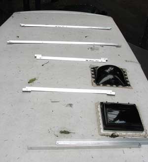
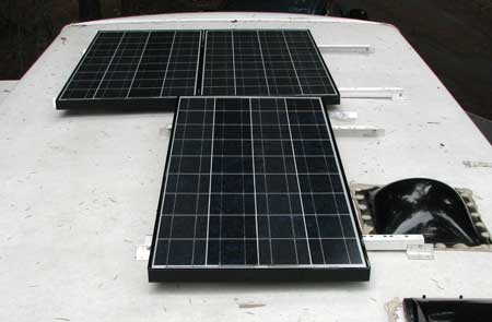
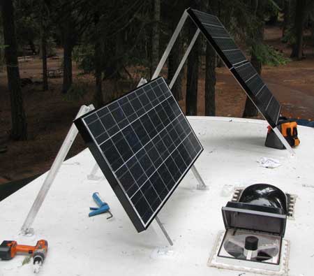
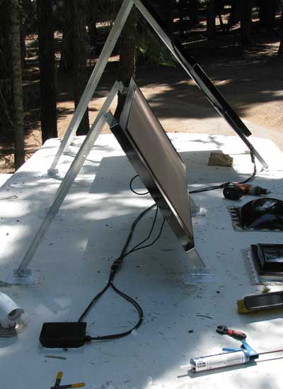
(Please read the disclaimer at the bottom of this page)I laid out the aluminum frames for the solar panels in the approximate positions where I intent to mount them. This is toward the front of the trailer. |
|
 |
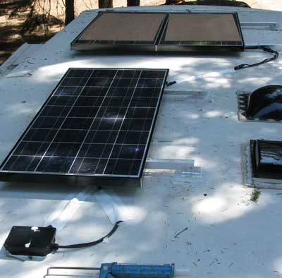
Here are the panels waiting at the rear of the trailer.
When choosing the front of the trailer, I have several reasons. I need to have as short a wire as possible leading from the panels to the charge controller. That means I need the panels to be close |
|
| to the hole I will drill into the roof to lead the wire to the controller. During the winter, the panels will be tilted up to point at the sun which will be low in the sky. We also want the sun to shine in our living area windows to help warm the trailer in the colder weather. Finally, I don't want any shadows landing on the panels from roof things like the air conditioner, vent lids or each other. Even a small shadow will nearly disable the entire panel. |
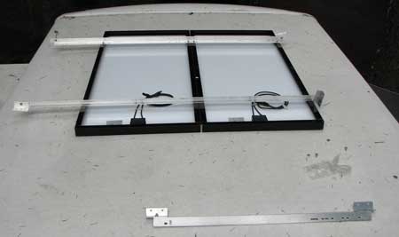
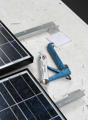
| My plan for today was to complete all the roof-top installation. However, the weather would not cooperate. It rained all night so I got a late start and the rain was threatening all day. I chose to get as much done as I could taking everything one step at a time. The frames mount very easily to the panels using stainless steel bolts. I have the panels upside down with the junction boxes toward the rear of the trailer where the combiner box will sit. This unit will flip over from left to right (the feet on the left will be on the right). |
 |
|
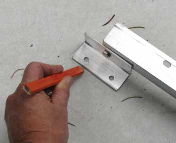 |
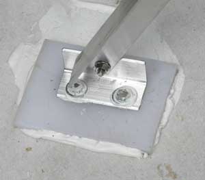
I called Carriage to learn the thickness of the roof material, it's 1/2 inch plywood. I want the 5/16" lag bolts to have a little more to bite into so I plan to set the feet onto 1/2" of plastic. I cut a plastic kitchen cutting board for this purpose. I also want the frames to be further off the roof to allow for better cooling and I don't like the idea of the metal feet sitting directly on my rubber roof. I'm marking the location of the feet so I'll know where to set the plastic pads. |
|
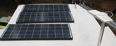
| Both panel frames are assembled and ready for permanent attachment to the roof. During the summer months, there is no need to angle the panels unless the trailer is parked in the northern part of the USA. Even then, they will not have to be angled much. Another consideration when choosing a location is the space to the top of the panels. I need enough space so I can comfortably walk on that side of the roof (without falling off) and lift the panels into position. Still, I can't have one set laying a shadow on the other. |
 |
|
 |
Once the pad locations have been marked on the roof, I will use Dicor as a glue and sealer. I make a box and "X" with the Dicor on the bottom of the pad and place the pad into location. I began with the larger frame thinking that I had more options in placing the smaller frame. There are always events that are not planned. I thought I was ready for everything but when I place the four plastic pads in the forward part of the trailer to fit the larger frame they began to slide. The forward part of the trailer roof is at a slight angle so the pads where sliding downhill. When I put the feet into the pads, the entire unit began to slide downhill. That meant I had to hold it in place while I measured and then drilled the lag bolt holes. It's already frightening enough drilling holes into the roof of my trailer. The sliding frame made it even more likely that I might drill a hole in the wrong location. Some how I managed with only two hands and two feet to help keep the frame in place. |
|
| You can see how much the pad slide before I was able to stop it. I used 5/16" x 1.5" stainless steel lag bolts. These were like buying gold, $1.19 each and I needed 16. I used galvanized washers as spacers because the top 1/4" of the bolt was not threaded and I wanted as much thread biting into the roof and plastic as I could get. I drilled a 7/32" pilot hole through the plastic pad and roof, then filled the hole with Dicor. I threaded the 5/16" lag bolt through the foot and twisted it into the pad and roof using a ratchet wrench. I'm feeling very secure that the Dicor will eliminate any possible water leaks. |
 |
|
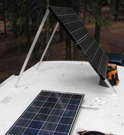 |
It really doesn't look like much space behind the large frame for me to walk and lift the frame into place but their really is. I lifted it to maximum so I could judge where it might project a shadow. That would help me decide where to install the smaller frame. Note that the feet of the frame must be exactly right to allow the frame to be bolted flat to the roof for travel and for summer months. I love the way this frame holds the panels about a foot off the roof. Much better for cooling and very helpful with trying to keep roof top shadows from ruining the potential charge from the panel. These frames seem very sturdy and simple. They came predrilled to fit my Mitsubishi 125 panels perfectly. |
|
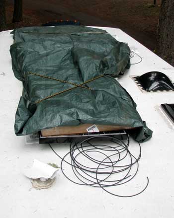
| Here they are. Both in the upright angle. There will be no shadows from the open vent and only a very early morning shadow from the larger frame onto the smaller frame (if any at all). The Mitsubishi panels use a special plug in style wire connector to each junction box. I have 15 feet of wire for each lead, that's enough to get the wire to the combiner box. I've laid the panels flat and covered with plywood over each panel then the cardboard boxes they came in. I put a plastic tarp over everything then bungee corded to keep everything in place. I won't actually be using these until September. I |
 |
|
|
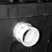
bought them early because I've learned that practically every community college in America will be training solar installers because of the stimulus money going to alternative energy projects soon. I'm afraid that will increase the price of solar panels. Why protect the panels so well? Take a look at the tree hanging over our trailer. See all those dead limbs waiting for the next wind to blow them loose. Note the holding tank vent? The combiner box will go next to that vent and on this side of it. There is a small space where I can drill a hole for the wire to pass through the roof. |
|
|
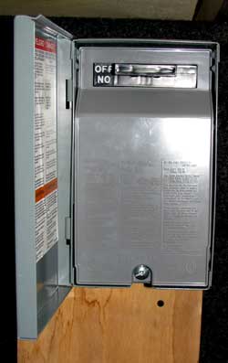 |
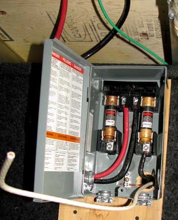
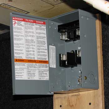
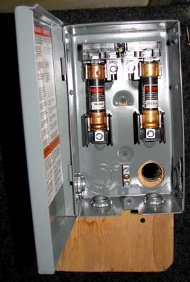
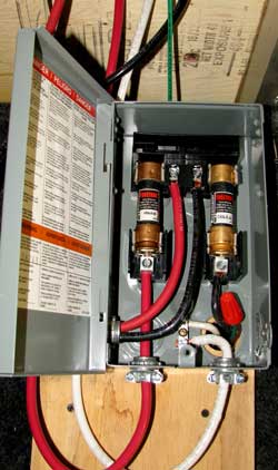
May 5, 2009: I've installed the fused pullout disconnect panel in the basement. Both the solar current coming from the panels and the current leading to the batteries from the charge controller can be disconnected by pulling the on/off lever. The positive line from the solar panels passes through a 45 amp fuse then on to the charge controller. The positive line coming from the charge controller passes through a 60 amp fuse then on to the batteries. Note that the lever currently reads "off". Pull the lever, turn it over and push back in place and it says "on". Notice the hole in the bottom right of the disconnect box. This is where the #6 AWG wire will enter the box from the combiner box and the solar panels.
Here is a great site to calculate the size wire you need for your 12 volt system. You need to know the "load" (amperes) the wire will carry and the length of the run. |
|
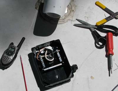
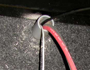
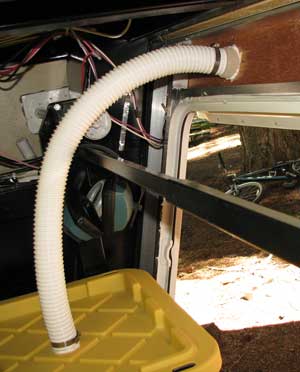
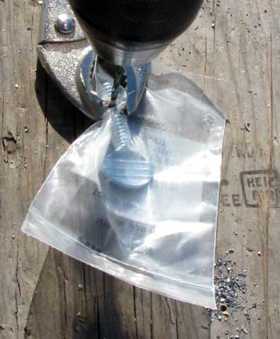
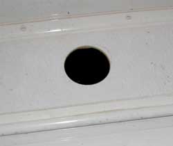
| May 9, 2009: Today was the day to finish the roof installation since I got rained out on my start day. I thought the most difficult task would be to feed the #6 wire through the roof. There is a small triangular shaped space where the tank vent comes through the roof. This space already has wires passing through and a hole in the ceiling where wires feed to the AC electrical panel. All I need to do is drill a hole in the roof and pass the solar wire through the roof hole and through the already-drilled ceiling hole into that space and I'll be home-free. You can see the vent at the top of the photo. The vent cover must be able to rotate 360° without hitting |
 |
|
 |
the combiner box. This means I can't drill my 3/4" roof hole directly over the existing ceiling hole. I'll need to feed the solar wire at an angle to find the ceiling hole. I used one of Gwen's discarded knitting needles to find the ceiling hole then fed the solar wire over the top of the needle following it to the ceiling hole. I couldn't believe it was that easy. Gwen kept in touch using the walk-talky to let me know that she caught the solar wire on it's decent.
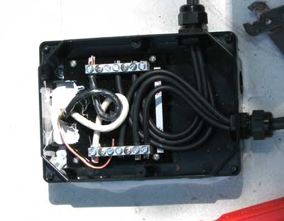
I brought all positive panel wires into one combiner box knock-out and all negative wires into another. This is wiring the panels in parallel rather than series. Wiring in parallel means I have 17 volts with 22 amps current in the
|
|
| wire so I chose #6 wire. Had I wired in series, I would have had 51 volts and about 7 amps current which would have called for a smaller wire into the coach but a different charge controller. I liked the idea of parallel because a shadow on one panel would not affect the other panels. In wiring in series, the whole system would be affected by anything affecting any ONE panel including shadows. Note that I have plywood over the panels during installation. Surprisingly, during much of the wiring, the panels were in direct sunlight and I didn't want to get shocked. The combiner box is screwed and glued to the roof using Dicor as the glue and roof sealant. The panel wire is highly UV resistant but I still wanted to run as much of the wire as I could under the panels to give additional protection to the wire. |
 |
|
 |
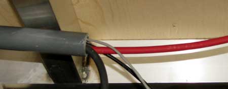
I did use wire clips sealed with Dicor at several key locations. |
|
The roof installation and wiring is complete. I used Eternabond tape in some locations to help hold the wire in place and protect the wire from direct sunlight. Eternabond is great stuff to have on-hand for roof repair and in this case, to hole solar wire in place.
I've begun to put the plywood back over the panels to protect from falling tree branches. I'll also cover the panels with the cardboard boxes they were shipped in. Both set of panels are then covered with a plastic tarp to keep the cardboard dry. The panels are bolted in place and ready for travel. When it comes time to move, I'll just remove the tarp, boxes and plywood and we'll be rolling. Now on to wiring the controller. |
 |
|
 |
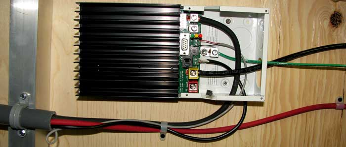
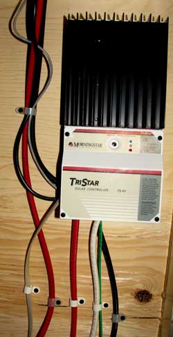
May 11, 2009: I've begun the wiring of the Morningstar Tristar 45 charge controller and the batteries with the pullout cutoff switch. After situating the conduit, I pushed the #6 welding wire battery cables, temperature sensor and voltage sense wires through the conduit. The batteries will sit in a case located in the front storage area. The Cameo battery compartment is large enough for two batteries but not four. |
|
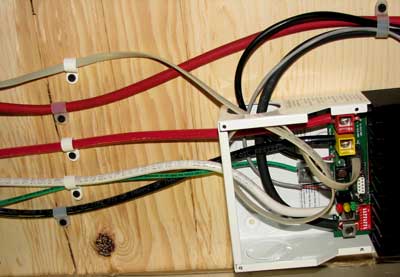
| All four cables pass through four feet of conduit into the middle storage area where the controller will be mounted to the roof of the storage area. The controller is small enough to fit between the aluminum floor joists and is completely out of the way in the storage area. In this photo the controller is |
 |
|
|
 |
partially wired with the solar common wire and battery positive wire yet to be connected. The positive from the battery and the positive from the solar panels must have a cutoff switch. I'm using a pullout cutoff switch with 45 amp fuse from the solar panels and 60 amp fuse from the batteries. In the photo above the negative battery wire is connected directly to the controller while the positive (red) wire passes the controller on the way to the switch. The red wire will pass through the 60 amp fuse and then back to the controller. The tiny gray wire is the battery temperature sensor. The controller voltage will vary depending upon the temperature of the batteries. The tiny black wire is the voltage sensor wire. It is charge sensitive so the positive lead must be connected to the positive side of the battery while the negative lead is connected to the negative side. The whole unit is grounded to the frame by the green wire. I'll finish the wiring another day. It's too late to continue today. |
|
| May 16, 2009: Today will be the day to complete the solar panel wiring. The charge controller is mounted to the ceiling of the storage bay. I only had two wires to complete this installation plus the remote meter wire. Click the photo to the right to enlarge. I've replaced the faceplate and completed the wiring of the pullout disconnect box. The ground wire is wirenutted and sent back behind the panel. |
 |
|
|
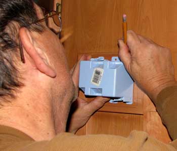 |
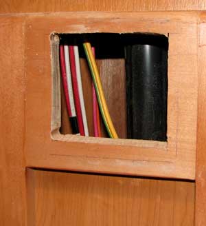
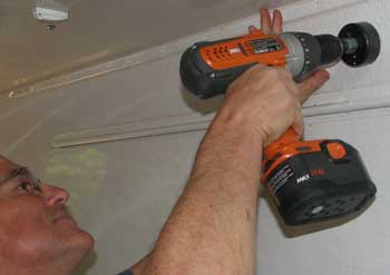
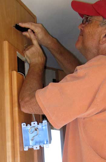
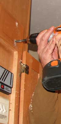
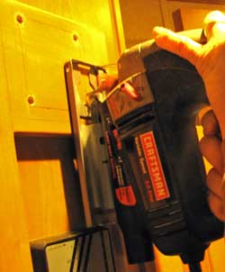
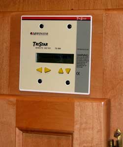
Only the remote meter is left to install. The ideal location is with all the other gauges. Fortunately the frame is large enough to fit the meter faceplate. I mark the size of the opening then drill four holes at the corners. A sabresaw is used to cutout the hole. I know there are wires and a tank vent pipe behind this wall so I'm careful to have only as much blade needed to cutout the hole. I don't want a long blade to pick up a wire behind or nick the vent pipe. |
|
|
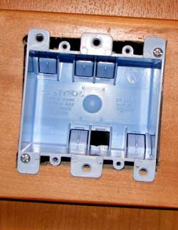
| You can see the wires and vent pipe behind this wall. As it turns out, there is plenty of room behind the wall. I mount a two gang receptacle box and feed the meter wire through the box which ends up behind the wall in the storage bay. Exactly where I want it. I bring the meter wire over the wall and connect to the charge controller. The meter is in place and ready for operation. The next step is to prepare the battery box for the batteries. That will be tomorrow's job. |
 |
|
|
| May 17, 2009: The final step to wiring in the solar panels is to create a location for the four batteries. The Carriage Cameo has a pathetic battery storage location large enough for two batteries. I say pathetic because the battery storage is one of those economy moves Carriage did to keep the lower price point on the Cameo. The batteries are nearly impossible to service in the location they created and tiny, even for two batteries. I must drill a hole above the front storage compartment for the vent/hose/face plate kit. I did a lot of |
 |
|
|
 |
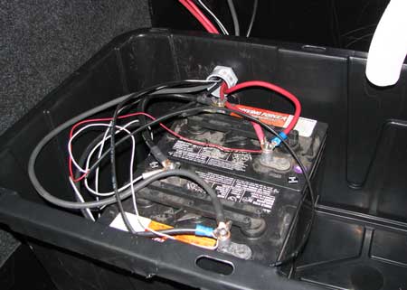
searching for the right battery case. It had to be large enough to fit four Trojan T-105 batteries but small enough to fit the space. I finally found just the right case at Home Depot. It advertises that it will hold 750 lbs. I will have 280 lbs of batteries in this case. Batteries give off hydrogen which must be vented to the outside since hydrogen is explosive (remember the Hindenberg?). Since hydrogen is much lighter than air (remember the Hindenberg again), I've vented the hydrogen out the top and installed a wire entrance about four inches down from the |
|
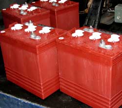
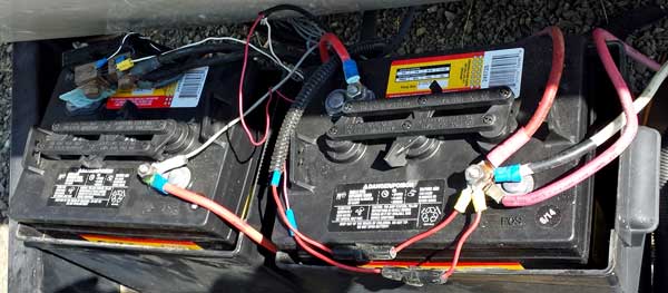
| top. I moved the old batteries into the case to try it out. The four batteries will fit well into the case. The batteries are connected to the converter/charger and to the solar charge controller (the heavy wires). The thin wires are the temperature sensor to report the battery temperature back to the charge controller and the voltage sensor to report voltage back to the charge controller. I still need |
 |
|
 |
to bring four heavy wires into the battery case for the two inverters. Currently I own only one inverter but will likely purchase a much larger inverter in the future so we can run the microwave, vacuum cleaner and, or course, the hair dryer. I plan to delay that purchase until the fall and hope to find a used inverter.
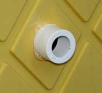
To the left you can see the battery case with the lid and 30 inch vent hose installed. It is surprising that I was able to get the huge battery case into the front storage and still have enough room to store everything that was in the storage compartment in the first place.
I'm using the old battery storage area to install the inverters. |
|
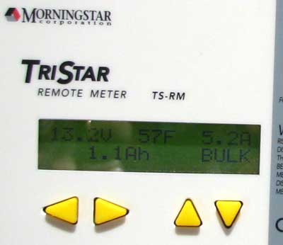
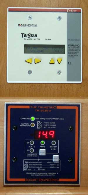
| May 23, 2009: I couldn't stand to wait, I removed the covers from the solar panels and waited until 12:30 pm. The trailer roof gets about 1 hour of sun beginning at 12:30 although all three panels never have sun at the same time. I generated my first AmpHour of power. The top right of the meter shows I'm generating 5.2 amps. I was concerned with the low reading but saw 14.2 amps generating when I had two solar panels in full sun. That's exactly right since each panel should generate 7.1 amps at 100% sun light. I had only about 5 minutes of 100% sunlight and only an hour of any registered sunlight at all. Still, I recorded 11.4 Ah before the charge went to zero. The volts went as high as 15.1 under full charge. The 57F is the temperature of the batteries. The amount of charge from the solar panels is adjusted for the temperature of the batteries. "Bulk" means that all energy coming from the panels is directed to the batteries. Once the batteries are full, the controller switches to "Float" to maintain the charge. |
 |
|
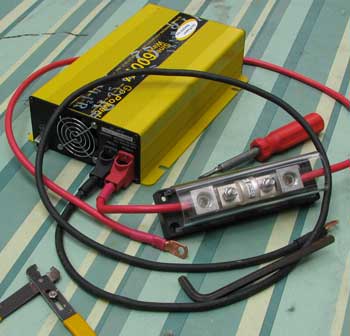 |
May 30, 2009: A solar system isn't much good if you can't use AC power in your RV. To do this, you need an inverter to change DC current to AC current. This is the 600W pure sine wave inverter I bought used from an Escapee friend at the desert rally in January. You connect the red and black wires to your batteries (the same batteries which are being charged by your solar panels). The red current wire (+) must have a 110 amp fuse between the inverter and the battery. 600 watts is 5.4 amps, so enough power for our computer network including the laptop computer, Internet modem, router, printer and monitors. You simply plug a standard 3 prong AC extension cord into one end of the inverter and the battery cables to the other end. |
|
| The easiest way to get the power into the coach is to plug your shore power cord directly into the inverter extension cord. Turn off the circuit breakers to the high power items in the trailer such as the microwave, water heater, air conditioning, electric heaters, in fact, most everything except the few items you want to power. Don't forget to unplug the converter, otherwise you've got a loop happening and the inverter won't |
 |
|
| work. My suggestion would be to get a 2,500 watt inverter, then you can manage you power easier and even use the microwave for a short cook. I intend to purchase and install a 2,500 watt inverter in addition to the 600 watt inverter. This will allow me to use the microwave, vacuum, coffee pot, toaster and other high amperage items for short periods. I can leave the larger inverter off when all I need is my computer and the Internet. Of course, they would be used one item at a time. I have created this shelf for the small inverter so I can fit the 2,500 watt inverter under it. It's nice to have both inverters in this compartment totally separate from the batteries and anything else which might fall on them. This is the Cameo battery compartment which was large enough for two batteries but not four batteries. The white wire hanging down from the inverter is the ground wire (I didn't have any green wire). You can click either photo to enlarge. |
 |
June 11, 2009: Today was my lucky day. I went to my favorite battery shop and learned that Trojan had sent them the wrong batteries today. Instead of receiving T105 batteries like I was prepared to buy, they shipped T125. The T105 is a 225 ampHour battery while the T125 is a 240 ampHour battery. They sold the T125 to me for the same price as the T105. I purchased four today with the interconnect cables. Since these are 6 volt batteries I will have 480 ampHours of storage. The Trojan manual says to use the top 2e0% of the battery so I can use 96 amps of stored energy plus the excess amps created by my solar system during the daylight hours. |
|
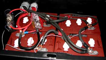
| June 13, 2009: The four Trojan T125 batteries are installed along with the fuses and connections for the two inverters. I had the interconnect wire custom made and I wish the battery shop had done a better job of judging the length, they are too long. I also wish the battery posts were slightly longer, with so many connections to each battery, they barely fit the post. If I must add any more I'll use a buss bar. Here is a nice link showing battery wiring. |
 |
|
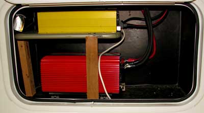 |
Both inverters fit into the battery bay. The 600 watt pure sine wave inverter on top and the 2000 watt modified sine wave on the bottom. The 600 watt inverter connects directly to the circuit which powers the Internet network, router, my computer system and printer. The 2000 watt inverter powers everything else in the coach by connecting directly to the AC panel. I have a manual switch between the AC panel and the inverter to be sure shore power is never connected to the inverter. I'm not putting this detail here because you need to know something about wiring and I don't want you to burn down your RV. |
|
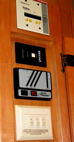
I'm carving out the control panel wall again for the remote on/off switch to control the Vector 2,500 watt inverter. The switch plate fits nicely inside the control panel cabinet and looks professionally installed. This switch will allow us to turn on full power when needed and off to conserve the batteries when not needed from inside the trailer. The 600 watt inverter has no remote switch so it must be turned off at the inverter box. It will likely be on much of the time to power the network and draws much less power than the large inverter. This completes the solar system installation for our fifth wheel.
|
 |
|
Sunday, August 2, 2009: I've been living on solar power for six weeks now. It worked about 90% as expected and is now working perfectly. My only problem was with the 2,500 Watt Vector inverter (original purchase). I just couldn't get it to work. I tried every trick and resetting it several times but finally gave up and returned it to InvertersRUS.com. Initially I was impressed with InvertersRUS because they shipped immediately and seemed to have competitive prices. However, when I wrote them for help, they ignored my emails and ignored my request for directions for a return until I filed an American Express dispute. They finally gave me return instructions where I had to pay for the return postage. They received the package on July 9, 2009 according to UPS and I'm still waiting for a refund credit to American Express. I absolutely DO NOT RECOMMEND dealing with InvertersRUS.com. I used them in the first place only because I thought a friend had recommended them only to learn that the friend had never dealt with them. I do expect to get a refund but only when American Express forces the issue. I did some research and found Vector inverters were sold online by Home Depot and at a better price than InvertersRUS. I chose to order only a 2000 watt inverter from Home Depot thinking that I really did not need the 2,500 watt power. Since I had the remote already installed, the 2000 watt was a bit smaller and could be easily connected to the wiring and remote. The package from Home Depot arrived quickly and with a return UPS shipping label in case there were problems. It installed quickly and works fine. I keep the 600 watt inverter as a backup to the Vector 2000 watt inverter but use only the remotely controlled Vector. It's been working fine since installed about three weeks ago.
You already know I use the Trojan T125 batteries which must be brought to a voltage of 14.8 for a couple of hours before going to float at 13.4. This voltage varies to temperature so if the temperature is low, say 67 degrees or lower, the batteries must be brought to a higher voltage, say 15.1. This can be a problem with some inverters because the inverter will shut down automatically at a high voltage. For the Vector, it is 15.5 volts ± .5. I've always been in warm weather since installing the Vector but if it shuts off at 15.5 - .5, that's 15 volts so I won't have AC power when the batteries reach their full charge cycle. All I can hope for is an automatic shut off of 15.5 or better. Watch for this when you purchase an inverter because many have a lower automatic shut off than 15 volts. (October 4, 2009 update: First, I highly recommend any brand OTHER THAN the Vector brand. Ours is still working but we are unable to run the DVD player using it and I believe it's because of the way the Vector creates the modified sine wave. Second, the Vector shuts down at 15 volts even though the stats indicate 15.5 volts ± .5. I've learned it's not such a problem anyway because you simply turn on enough lights to bring down the voltage, then turn on the inverter and whatever AC items you wanted to power, then turn off the lights. The AC load will likely keep the inverter below the cut off point.)
I have seen the amperage coming from my solar panels of better than 21 amps so I know all three are working as they should. Each one should put out 7.1 amps. in ideal conditions. The sun is high in the sky during these months so I should be getting a maximum return from my panels. I have noticed when the panels are even at a slight angle to the sun, the charge amperage is affected somewhat.
We are committed to solar. While camping at Gerber Reservoir (June, 2009) another camper offered to buy our Honda 2000 generator and we took him up on the offer. We are now solar only. We not only don't have to carry the generator as we travel but don't have to carry the gasoline to power it.
| Friday, February 26, 2010: My friends Dick and Ralph admire my new Yamaha generator. They both own the Honda 2000, the same one I sold back in June so they were envious of my new Yamaha. Yes, after having high expectation of surviving without backup power, I have yielded and purchase the Yamaha EF2000iS. The specifications are identical to the Honda but slightly lighter, less noise, has a fuel shut off valve and most important, it's blue. It's cost is slightly higher than the Honda but I shopped the Internet, and found Stalkups RV Superstore in |
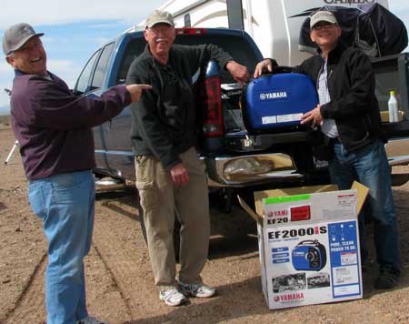 |
| Casper, Wyoming selling this generator for $879 including shipping. They also did not charge sales tax since it was shipped out of state. I had it shipped to the "Pack and Ship" store in Safford, Arizona who charged $3 for this service. The shipping time was less than 48 hours from Casper, Wyoming to Safford, Arizona. What is interesting about this purchase was that I did not have to pay the huge 10% Arizona sales tax. Had I found this generator in a local store for $879, I would have to pay another $87.90 in sales tax. Gwen and I have found that it is stressful to be solely dependant upon solar power. We are relatively big power users watching TV and using the Internet daily. On cloudy days, we can't store enough power to do everything we wish to do, without sacrificing TV, Internet or both. During multiple cloudy days which we experienced in Truckee, California and during a few stormy days in Arizona, it really becomes stressful. The generator eliminates the stress, even though we don't expect to use it on a regular basis. It's also a great backup for the air compressor and microwave. I'm no longer a "purist" like my friend Handy Bob below. I have added a new feature to my "Weather Data" page to show not only how much solar energy I've stored for the day but whether I have used the generator (G) that day. Running the generator WILL store energy in the batteries through the converter. Generally, if the batteries are in a low state, my converter will charge at the rate of 55 amps for the first 30 minutes to 1 hour before dropping to a lower charge rate. Even a small amount of solar charge will top them off at that point. |
|
You do have to manage your power usage during the day. We are often on the Internet first thing in the morning which requires AC power and I use AC to make a cup of coffee while Gwen uses AC to blend a smoothie for breakfast. We must consciously turn everything off during the best solar times of the day to allow the batteries to recharge fully before the evening. On a cloudy day, we would need to be even MORE conscientious about this. So far, we've had no problems.
I highly recommend you read the information at HandyBobSolar.com before choosing any solar installation whether you do it yourself or have someone do it for you. |
|
|
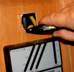
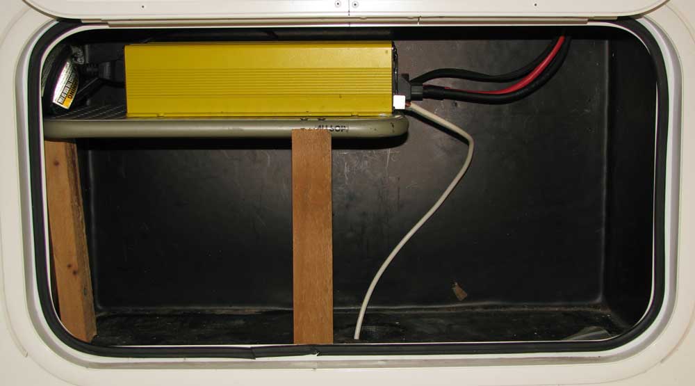
| Monday, November 23, 2009: Since installing the Vector 2000 inverter, we've been operating the whole system on the one inverter mainly because we enjoy the remote control switch on the Vector to turn it on/off. The disadvantage to using only ONE inverter is turning on a high powered inverter when only a small wattage is needed. The Vector is also only 85% efficient which means the Vector draws more power than it should just because it's in the "on" position. Third, the DVD player does NOT like the modified sine wave power produced by the Vector and will not work. Following a suggestion from HandyBob, I installed a remote power switch to the GoPower 600 watt pure sine wave inverter (yellow inverter in the photo above) by soldering the toggle switch you see in the photo (at right) in parallel with the switch mounted on the GoPower case. I wired the 600 watt inverter directly to the single circuit which powers the entertainment center, TV and network. The Vector is used to power everything else. The toggle switch is located in the same cabinet with all the other control switches. I really like the idea and operation of having two inverters and my electronic systems really likes the pure sine wave power. Note that 600 watts is plenty of power to have the entertainment center, TV and network all working at the same time. |
|
 |
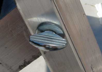
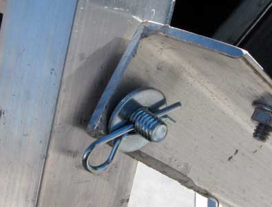
Sunday, February 21, 2010: I've changed the nut and bolt system of raising the solar panels. Using a nut and bolt is very slow and requires tools. I picked up 8 thumb screws at the hardware store and drilled each with two holes to make the width adjustable. I've protected both sides of the thumb screw with washers. This allows me to quickly raise or lower the panels without the use of tools. In addition, I made the thumb screws long enough to secure the support arms with the panels while traveling. I no longer need to store the support arms in a storage shed then carry them to the roof each time they are needed. |
|
 |
 |
|
| Description |
Amount |
| (3) Mitsubishi 125 watt Solar Module |
$1,890.00 |
| Frame to hold two modules |
86.00 |
| Frame to hold one module |
68.00 |
| (3) Cable sets for each module |
90.00 |
| Morningstar/Tristar 45 Charge Controller |
165.00 |
| Tristar remote display meter |
125.00 |
| Tristar remote battery temperature sensor |
30.00 |
| (2) 60 amp fuses between controller and battery |
14.00 |
| Battery container to hold (4) batteries |
9.98 |
| (16)Stainless steel lag bolts for module frame feet |
19.04 |
| (16) Galvanized washers for frame feet |
1.76 |
| (3)2' x 4' plywood to protect module face |
11.91 |
| (2) tubes Dicor to seal roof around mounting holes |
15.98 |
| (1)Pull out fused disconnect to break current between modules and charge controller and between the controller and battery bank |
24.98 |
| Battery vent hose and cover |
11.89 |
| (11 feet) 6AWG wire from combiner box to charge controller |
13.97 |
| Pull out disconnect to disconnect the inverter from the system electrical panel |
6.74 |
| 110 amp fuse and fuse holder between the battery bank and the 600 watt inverter. |
50.25 |
| Combiner box |
59.90 |
| Battery cables to charge controller |
40.90 |
| Misc. wire |
15.74 |
| Wire clips |
.67 |
| Modify battery case |
3.06 |
| 600 watt inverter to battery cables |
17.50 |
| AC panel to inverter wire |
13.40 |
| AC wire for 2,500 watt inverter |
9.80 |
| 2,500 watt inverter |
321.99 |
| (4)Trojan T125 with interconnect cables |
454.18 |
| Battery to 2500 watt inverter cables |
45.02 |
| Total on June 13, 2009 |
$3616.66 |
|
Wednesday, June 16, 2010: When you look at the ampHour reports on the Weather Data chart, you should have some questions.
Question: Why do you get a full charge on some days when you get only a minimal number of AmpHours generated? For example, March 12, 2010, you got only 71.4 AmpHours yet the batteries were fully charged. Answer: This must have been a day when we left early in the morning to explore so no one was home to use any power. When the batteries are fully charged, the charge controller meters the solar ampHours to the batteries because they no longer need a charge so the recorded ampHours are few.
Question: Why don't you get a full charge on some large ampHour days? For example, April 14, 2010 you got 157.8 ampHours, yet the batteries were not fully charged. Answer: Sometimes we will begin using power early in the day, say turn on the Internet or watch the French Open tennis match which must be watch before noon our time. So the power is coming from the solar panels but instead of all the power going to recharge the batteries, some is siphoned off to power appliances we are using. The batteries never get quite enough ampHours to bring them to full charge. Generally, if we are able to leave appliances off in the morning (when the French Open is not in season) and allow the batteries to come to full charge THEN turn on the Internet or TV, the batteries will STAY at full charge until late in the day when the sun is at too great an angle to the panels. Another situation is using a lot of power on the previous evening draining the batteries to a lower state. A lot of ampHours are needed to bring those batteries back to a full charge. Perhaps the morning is clear so we begin to get a good charge from the panels THEN clouds begin to roll in. We get a good charge only when the sun peaks through the breaks in the clouds. This keeps the charge controller passing through all the ampHours available but stretches the ampHours over the entire day (as long as 14 hours of daylight) but the batteries never quite get to a full charge.
Question: Why is there such a huge difference in ampHours to charge the batteries when you are on shore power (sp)? For example on April 30, 2010 it took 85.9 ampHours to charge the batteries yet on May 8, 2010 it took on 5.4 ampHours for a full charge. Answer: This has to do with the way I have wired our trailer. I use TWO inverters. One inverter is a 600 watt pure sine wave inverter and is dedicated to our entertainment center and computers. The other inverter is a 2000 watt modified sine wave inverter used to power everything else. In general, I leave the 600 watt inverter on and connected even when we are using shore power. This means that ONE circuit is still getting all its power from the batteries but the batteries are being recharged from the solar panels as well as the converter. The converter STOPS charging the batteries at about 13.4 volts but to be fully charged the batteries MUST be brought to 14.8 volts plus or minus a few volts depending upon the temperature. These extra ampHours to bring the batteries to full charge come entirely from the solar panels NOT the converter so you might see 85.9 ampHours just because we are using the entertainment center or computers. On the other hand, it only takes about ten minutes to switch the wiring back to eliminate the inverter where ALL power is coming from the shore power connection and NOT the inverter. In that case, NO power is coming from the batteries and it takes only a few ampHours per day to maintain a full charge on the batteries. |
| Sunday, December 12, 2010: Today was a project day. I've been putting this off for some time. I'm adding another meter to monitor my solar charging and battery conditions. I've mentioned Solar Bob previously. He is camped near us in Bouse and has installed many solar systems the correct way. His systems actually work. He convinced me for the need of the Tri-Metric meter to monitor the conditions of the batteries and of the loads I placed on the batteries. My Morningstar remote meter is great for controlling the charge controller remotely and for knowing the total AmpHours downloaded from the solar panels but does NOT tell me how many AmpHours have actually been stored in the batteries NOR does it tell me the load on the batteries of each electrical item we use in the RV NOR does it tell us the percent of full charge in our batteries. The Tri-Metric meter WILL give that information and plenty more. From the questions asked of me by readers, I can see that many still do not understand the use of solar power in an RV. We have been VERY happy with our solar system but still use a |
 |
| generator occasionally for high power usage items and to "save us" from a cloudy day. The sole purpose of the solar panels is to charge the batteries. Our maximum rate of charge in full sun light is about 23 Amps. In theory, if we had full sun light, then, for 10 hours we could store 230 Amps in our batteries if they can hold that much. We have (4) 6 volt batteries where each holds 245 AmpHours. Multiply that time (2) is 490 Amphours at 12 volts. That's the total storage capacity of our batteries. When we are using the Internet and our two laptops plus DVR is on (perhaps recording a TV show) we are using about 11 Amps. No lights are on or we would be using more Amps. If we use this amount of power from 6 pm to 11 pm we will drain (11) x 5 (hours) = 55 AmpHours from our batteries. If we turn on the TV (ours is a real power hog) the 11 Amps will jump to 22 Amps. Assume we watch TV for (3) hours so add 33 AmpHours to the 55 for a total of 88 AmpHours drained from the batteries in one night. The rule of thumb is to use about 80% of full battery capacity although it does not hurt the batteries to use much more than that if you bring them back to full charge the next day. So 490 - 88 = 402, 402/490 = 82%. When we start turning on lights or pump water, for example, we may use more than 80% in a night. The next day, the solar panels will begin replacing the drained Amps as soon as the sun comes up but at a very low current to begin with since the sun is very low in the sky. In the winter months, our panels will be putting our maximum Amps between 11am and 3pm with slightly less Amps the rest of the hours depending upon the position of the sun to the angle of the panels. During the summer months it's far easier to get many more Amps because we have many more hours of daylight and the sun is higher in the sky. Of course, any clouds will affect the panel current dramatically. Also, assuming our panels are putting out a maximum of 23 Amps, but it's Sunday and we are watching football on TV, 11 Amps is taken to run the TV so only 12 Amps will be stored in the batteries each hour. For this reason, we will normally schedule vacuuming in the early morning to give the batteries the rest of the day to recover from the vacuum power drain. Finally, the job of the charge controller is to monitor the voltage to the batteries. The charge controller will send all Amps to be stored in the batteries until the batteries are fully charged and begin to reject Amps. When that happens, the charge controller will monitor the voltage to the batteries to be sure the voltage does NOT go above a preset limit. In my case, that limit is 14.8 volts at 77 degrees, more in colder weather and less in hotter weather. That can be a good time to use electrical appliances because the panels are still putting out maximum amps but the batteries can't use the power so we can consume power without lowering that stored in the batteries (within reason). |
|
I already mentioned our two inverters. This helps us manage our power usage as well as supply "pure sine-wave power" to our electronics. This has worked very well for us although we should have gone with a larger inverter than 2,000 watts to power the microwave. The 2,000 does a very poor job (but it does work). I could also be the Vector inverter brand which I DO NOT RECOMMEND. We also manage our electrical appliances and electronics with power strips, keeping key power strips in the OFF position when those items are not being used. For example: The stereo/DVD player is kept OFF with a power strip when not in use. I also unplug the DVR and TV from a power strip when not in use. We have a number of power strips to help us manage power. All refrigerators require DC power even when on the LP setting. Ours pulls about .8 Amp so not significant but will be seen as a drain on the batteries even when everything else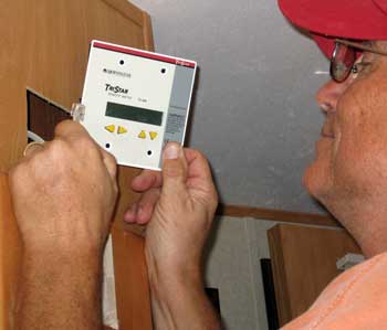 |
 |
|
| is off. Finally, you CAN NOT bring your batteries to a full charge using a generator. That's because you plug the coach into the generator which charges the batteries through the converter. My Trojan batteries must be brought to 14.8 volts at 77 degrees (higher if colder) and held there for three hours to get a full charge. I have one of the best converters which delivers 55 amps to the batteries until they reach 14 volts then it cuts back to a trickle charge thinking the batteries are fully charged. You can see all this on either of my meters. It takes solar panels with a programmable solar charge controller like the Morningstar to bring the batteries to proper full charge voltage. Also you can't equalize your batteries using your converter. When we know it's going to be a cloudy day we will often use the generator in the morning to give the batteries a boost then let the solar panels bring them the rest of the way to a full charge. All this is detailed at Bob's solar site if you care to read volumes about it.
To summarize the use of the two meters, the Morningstar remote meter tells me what is happening with the solar panels while the Tri-metric meter tells me what's happening with the batteries. I can read the number of AmpHours coming from the solar panels on the Morningstar meter, the total AmpHours in a day, battery voltage and battery temperature. With the Tri-metric meter I will know how many of the AmpHours coming from the panels is being stored in the batteries (some may be used in the trailer if appliances or electronics is on). I will know how much power each individual item in the trailer uses (like our power-hog TV uses 10 Amps while the LED light over the dining table uses 0.2 Amps). The Tri-Metric meter also counts out the total Amps used from the batteries at night then counts them back in while charging during the day. For example, the meter reports 60 AmpHours needed to bring the batteries back to full charge and counts down as they are being replaced ... 59 ... 58 ...57 etc. If my solar panels are putting out 20 AmpHours, I know it will be 3 hours to get the 60 AmpHours I need for a full charge. It will also tell me the percent of charge in the battery. For example, today was a cloudy day so my batteries came back to 95% of full charge from solar charging. Normally, they will be back to 100% between noon and 3 pm depending upon the amount of power we are using during the day. Finally, I can remotely start a battery equilization using the Morningstar meter. Using both meters, I can better manage my power usage and storage. |
| Saturday, January 1, 2011: That's right, this is a day for football. It's also the day I have started a new weather and solar data page. I'm explaining more of the solar operation and how to understand the data I'm providing. Weather has a lot to do with how much solar I get. Today was a near perfect solar day with the exception of the last hour when a few clouds obscured the sun. Still, my panels got about 98% of what was available. |
 |
Knowing that, 144.3 AH is the most I can get on one of the shortest solar days of the year. That's with panels lifted and pointed directly at the sun in the southern sky. Each day is a little longer than the previous day, however, so the prospects of getting more solar each day are good. So if it was such a good solar day, why didn't I get a full charge (100% rather than 95%) on the batteries when I started at 79%? Football and a 118 watt TV are the reason. Since this is a day of football and the TV is on most of the day, that's a draw of 10 amps just for the TV. Another 2 amps for the DirecTV DVR to send the signal to the TV means a total of 12 amps to watch TV. Maximum amps from the panels of 23 will start at about 11:30 and last to about 14:30 (less amps before and after this ideal sun and panel placement). So, at the best possible sun position my panels will send 23 - 12 amps = 11 amps to the batteries (note the electronics and computers to run the Internet are OFF or even less amps to the batteries). That is just NOT enough of a charge to bring the batteries to a full charge with such short days. Normally I would not use the generator with a 95% charge on the batteries but decided to use it since we will watch more football, have both computers and the Internet on and Gwen wants her lamp on so she can bead. Early in the evening, I shut down the generator, turned on both inverters, Internet is on, TV is on, Gwen's beading light is on, all of which creates a draw of -24.6 amps on the batteries ... a huge hourly draw, hence the use of the generator earlier.
Next, the low temperatures. This was the coldest day since coming to Arizona. How does that affect solar? My Morningstar charge controller is temperature compensated. The controller will bring the batteries to 14.8 volts to reach a full charge WHEN the batteries are at 77°. If the batteries are warmer, the controller will reduce the voltage. But today, the batteries were in the mid-40s so the controller needed to bring the batteries to 15.2 volts for a full charge (that happened yesterday). Hopefully you are getting the picture that a generator plus your converter WILL NOT bring the voltage to 14.8 and is NOT temperature compensated so the generator/converter combination has NO CHANCE to fully charge your batteries. Additionally, some inverters are very sensative to high voltage (15 volts and above). My Vector inverter WILL NOT work at 15 volts and above so unless I decide to bring the voltage down on cold days, I don't have AC power from that inverter. The smaller 600 Watt Go Power inverter is not as sensative and WILL work at 15.2 volts although it's "high voltage" warning light flashes. This is something to consider when making an inverter purchase.
Finally, the column "Cumulative AH" needs to be explained. I have installed Trojan T125 6 volt batteries. These are deep cycle batteries and should last 5 - 7 years if I take care of them. If discharged deeply, they must be recharged fully as soon as possible. The more cycles of less than a deep discharge, the longer the batteries will last. Of course, keeping the water level in the batteries above the plates and running equalization charges periodically is a must for healthy batteries. I installed a Tri-Metric meter on December 12, 2010 which gives be a huge amount of information about the batteries. The cumulative AmpHours issued by the batteries is now available to me from the Tri-Metric meter. It is like the odometer in an automobile. Obviously, the batteries have a certain number of cycles in their life. Eventually, they will need to be replaced when efficiency is reduced. The knowing the number of cumulative AmpHours will help to know how much life is left in the batteries. The batteries were installed in June, 2009 and the meter in December, 2010, so the batteries have already given up 1.5 years of Amps. I plan to interpolate the total number of AmpHours once I have a record of what they are currently doing. Having this "cumulative AmpHour" data, will help me predict the performance of my next set of batteries.
I hope you see that you must manage your power carefully to get full use and energy savings from a solar charging system. What will help are energy efficient electronics (such as a 38 watt TV which is the same size as my 118 watt TV). Longer days will help. Another solar panel would help but the cost can't be justified and we may not have the space on the roof of our RV. When you have a solar charging system and you are like me, you are watching every watt coming in and going out (what fun!).
May 31, 2013: A new saga! Yesterday I began moving this entire solar charging system to another RV. We have "downsized" ... just tired of towing 16,000 lbs. We've kept the Cameo fifth wheel as a permanent "home base" but will continue traveling in something 7,000 lbs lighter. |
___________________________________________________________________________
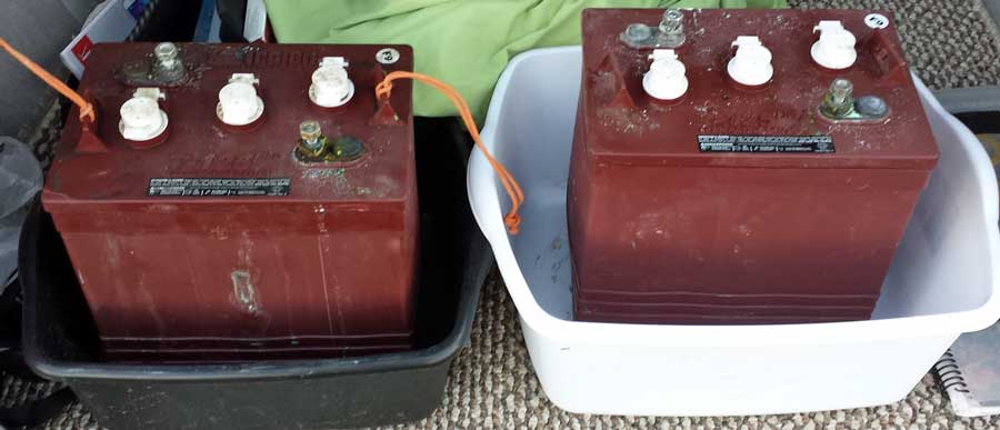
July 30, 2014: The Trojan T125 batteries I purchased five years ago must be replaced. I have loaded the "core" of two batteries into the car and taking them to Costco. I've been talked into the purchase of two "golf cart batteries" which Costco sells for $40 less per battery. They are identical in size and weight to the Trojan batteries and my friend, Wally, who recommended them has been using them for solar storage for eleven years. He says they last 5 years. Well, that's how long the Trojan batteries lasted me. I'm giving the Costco batteries a try. |
_________________________________________________________________________
 Friday, August 1, 2014: The new Costco batteries have been installed in the Alumascape. I was concerned because they were not fully charged however, I checked on them this afternoon after a morning of solar charging and they are fully charged NOW! Friday, August 1, 2014: The new Costco batteries have been installed in the Alumascape. I was concerned because they were not fully charged however, I checked on them this afternoon after a morning of solar charging and they are fully charged NOW!
|
|
|
| |
| |
| Disclaimer: In the story above, I'm describing my solar and installation choices. I am not a professional solar installer nor am I an electrician. I have made what I believe to be the best choices for me but have no idea if these would be good choices for you or even safe for you. If you choose to purchase the products I've mentioned above or use the same installation procedures you are doing so at your own risk. |
|
|
|


